Relay Terminology – Contactschadmin2022-06-22T03:02:03+00:001. Contact Forms
Denotes the contact mechanism and number of contacts in the contact circuit.
2.Contact Symbols
| Form A contacts
(normally open contacts) |
|
| Form B contacts
(normally closed contacts) |
|
| Form C contacts
(changeover contacts) |
|
Form A contacts are also called N.O. contacts or make contacts.
Form B contacts are also called N.C. contacts or break contacts.
Form C contacts are also called changeover contacts or transfer contacts.
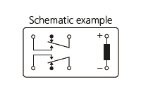
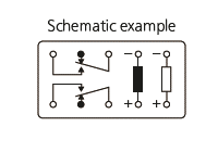
3.MBB Contacts
Abbreviation for make-before-break contacts. Contact mechanism where Form A contacts (normally open contacts) close before Form B contacts open (normally closed contacts).
4.Rated Switching Power
The design value in watts (DC) or volt amperes (AC) which can safely be switched by the contacts. This value is the product of switching voltage x switching current, and will be lower than the maximum voltage and maximum current product.
5.Maximum Switching Voltage
The maximum open circuit voltage which can safely be switched by the contacts. AC and DC voltage maximums will differ in most cases.
6.Maximum Switching Current
The maximum current which can safely be switched by the contacts. AC and DC current maximums may differ.
7.Maximum Switching Power
The upper limit of power which can be switched by the contacts. Care should be taken not to exceed this value.
8.Maximum Switching Capacity
This is listed in the data column for each type of relay as the maximum value of the contact capacity and is an interrelationship of the maximum switching power, maximum switching voltage, and maximum switching current. The switching current and switching voltage can be obtained from this graph. For example, if the switching voltage is fixed in a certain application, the maximum switching current can be obtained from the intersection between the voltage on the axis and the maximum switching power.
| Maximum Switching Capacity |
 |
| Example: Using TX relay at a switching voltage of 60V DC, the maximum switching current is 1A.
(*Maximum switching capacity is given for a resistive load. Be sure to carefully check the actual load before use.) |
|
9.Minimum Switching Capability
This value is a guideline as to the lowest possible level at which it will be possible for a low level load to allow switching. The level of reliability of this value depends on switching frequency, ambient conditions, change in the desired contact resistance, and the absolute value. Please use a relay with AgPd contacts if your needs analog low level loads, control, or a contact resistance of 100 mΩ or less. We recommend that you verify with one of our sales offices regarding usage.
10.Contact Resistance
This value is the combined resistance of the resistance when the contacts are touching each other, the resistance of the terminals and contact spring. The contact resistance is measured using the voltage-drop method as shown below. The measuring currents are designated.
Test Currents
| Rated Contact Current or Switching Current (A) |
Test Current(mA) |
| Less than 0.01 |
1 |
| 0.01 or more and less than 0.1 |
10 |
| 0.1 or more and less than 1 |
100 |
| 1 or more |
1,000 |
The resistance can be measured with reasonable accuracy on a YHP 4328A milliohmmeter.
In general, for relays with a contact rating of 1A or more, measure using the voltage-drop method at 1A 6V DC.
11.Maximum Carrying Current
The maximum current which after closing or prior to opening, the contacts can safely pass without being subject to temperature rise in excess of their design limit, or the design limit of other temperature sensitive components in the relay (coil, springs, insulation, etc.). This value is usually in excess of the maximum switching current.
12.Capacitance
This value is measured between the terminals at 1kHz and 20°C 68°F.


