
- CONTACT & COIL
- CHARACTERISTICS
- Model Info.
- Dimensions
- Precautions
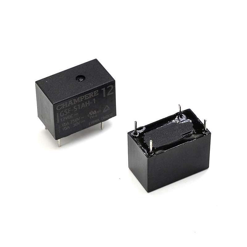
Description
| CONTACT RATINGS | |||
|---|---|---|---|
| Contact Form | 2C, 3C, 4C | ||
| Contact Res. | ≤100mΩ | ||
| Contact Material | Ag Alloy (AgSnO2, AgSnO2In2O3) | ||
| Rated Load | FORM C | ||
| NO | NC | ||
| 7A 240VAC/28VDC(2C) 5A 240VAC/28VDC(3C) 5A 240VAC/28VDC(4C) |
7A 240VAC/28VDC(2C) 5A 240VAC/28VDC(3C) 5A 240VAC/28VDC(4C) |
||
| Max. Current | 7A | 7A | |
| Max. Power | 1,680VA/196W | 1,680VA/196W | |
| Max. Voltage | 240VAC/28VDC | ||
| Min. Load | 100mA at 5VDC | ||
| COIL DATA | |||||
|---|---|---|---|---|---|
| DC Coil | Approx. 900mW | ||||
| Rated Voltage (VDC) | Operate Voltage (VDC) | Release Voltage (VDC) | Max. Voltage (VDC) | Nominal Current (mA) | Coil Res. (Ω)±10% |
| 12 | ≤9 | ≥1.2 | 13.2 | 75 | 160 |
| 24 | ≤18 | ≥2.4 | 26.4 | 37.5 | 640 |
| 110 | ≤82.5 | ≥11 | 121 | 8 | 13,444 |
| 220 | ≤165 | ≥22 | 242 | 4 | 53,778 |
| AC Coil | Approx. 2VA | ||||
| Rated Voltage (VDC) | Operate Voltage (VDC) | Release Voltage (VDC) | Max. Voltage (VDC) | Nominal Current (mA) | Coil Res. (Ω)±10% |
| 12 | ≤9.6 | ≥3.6 | 13.2 | 100 | 42 |
| 24 | ≤19.2 | ≥7.2 | 26.4 | 50 | 168 |
| 110 | ≤88 | ≥33 | 121 | 10.9 | 3,529 |
| 220 | ≤176 | ≥66 | 242 | 5.4 | 14,116 |
Additional information
| Weight | 35 g |
|---|---|
| Dimensions | 27.3 × 21 × 34.7 mm |
| Max. Capacity | 5A 240VAC/28VDC, 7A 240VAC/28VDC |
| Contact Form | 2 Form C, 3 Form C, 4 Form C |
| Operate Time | ≤15ms |
| Release Time | ≤10ms |
| Insulation Resistance | 1,000MΩ (@500VDC) |
| Dielectric Strength (I/O) | 1,500VAC 1min |
| Dielectric Strength (O/O) | 1,000VAC 1min |
| Shock Resistance | Non-energized: 10G; Destructiion: 100G; Malfunction: 10G |
| Vibration Resistance | Destruction: 10 to 55Hz (Double Amplitude); Malfunction: 10 to 55Hz (Double Amplitude) |
| Ambient Temperature | Operating: -40℃ – 70℃ |
| Ambient Humidity | Operating: 5% – 85% |
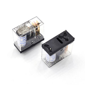
| Mount Type | Vertical Quick Connector, PCB Pin (DIP/TH) |
| Color | Trasparent |
| Model Number Legend | ||||||||||||||
|---|---|---|---|---|---|---|---|---|---|---|---|---|---|---|
| GSY | – | F | 2 | C | – | P | L | / | 24VDC or VAC | |||||
| (1) | (2) | (3) | – | (4) | (5) | (6) | ||||||||
| (1) | Case Type: | Nil: Standard; F: Flange. | ||||||||||||
| (2) | NO of Pole: | 2: 2-Pole; 3: 3-Pole 4: 4-Pole. | ||||||||||||
| (3) | Contact Form: | C: Form C / Change Over. | ||||||||||||
| (4) | Pin Type: | Nil: QC; P: PCB Pins. | ||||||||||||
| (5) | Components: | Nil: Standard, No Component; L: With LED Indicator; D: With Diode; LD: With LED Indicator and Diode. |
||||||||||||
| (6) | Coil Voltage: | XX / XXX: Coil Voltage Value. | ||||||||||||
| Major Model Ordering Chart | ||||||
|---|---|---|---|---|---|---|
| Case Type | Contact Form | Capacity | Components | Pin Type | Model | Coil Voltage |
| Standard | 2PDT | NO: 7A NC: 7A |
Nil | QC | GSY-2C | 12VDC 24VDC 110VDC 220VDC 12VAC 24VAC 110VAC 220VAC |
| PCB | GSY-2C-P | |||||
| 3PDT | NO: 5A NC: 5A |
QC | GSY-3C | |||
| PCB | GSY-3C-P | |||||
| 4PDT | QC | GSY-4C | ||||
| PCB | GSY-4C-P | |||||
| 2PDT | NO: 7A NC: 7A |
LED INDICATOR | QC | GSY-2C-L | ||
| PCB | GSY-2C-PL | |||||
| 3PDT | NO: 5A NC: 5A |
QC | GSY-3C-L | |||
| PCB | GSY-3C-PL | |||||
| 4PDT | QC | GSY-4C-L | ||||
| PCB | GSY-4C-PL | |||||
When ordering, add rated coil voltage to model.

PRECAUTIONS REGARDING COIL INPUT
For the operation of AC relays, the power source is almost always a commercial frequency (50 or 60 Hz) with standard voltages of 6, 12, 24, 48, 120, 230 and 240VAC. Due to this, when the voltage is ohter than the standard voltage, the product becomes special model.
PRECAUTIONS REGARDING CONTACT
For the operation of AC relays, the power source is almost always a commercial frequency (50 or 60 Hz) with standard voltages of 6, 12, 24, 48, 120, 230 and 240VAC. Due to this, when the voltage is ohter than the standard voltage, the product becomes special model.
PRECAUTIONS REGARDING SOLDERING CONDITION
We recommend wave solder, the recommended temperature is 240°C 464°F to 260°C 500°F, and the time is 2s to 5s, time should no longer than 2s when temperature reach 250°C 500°F or above.