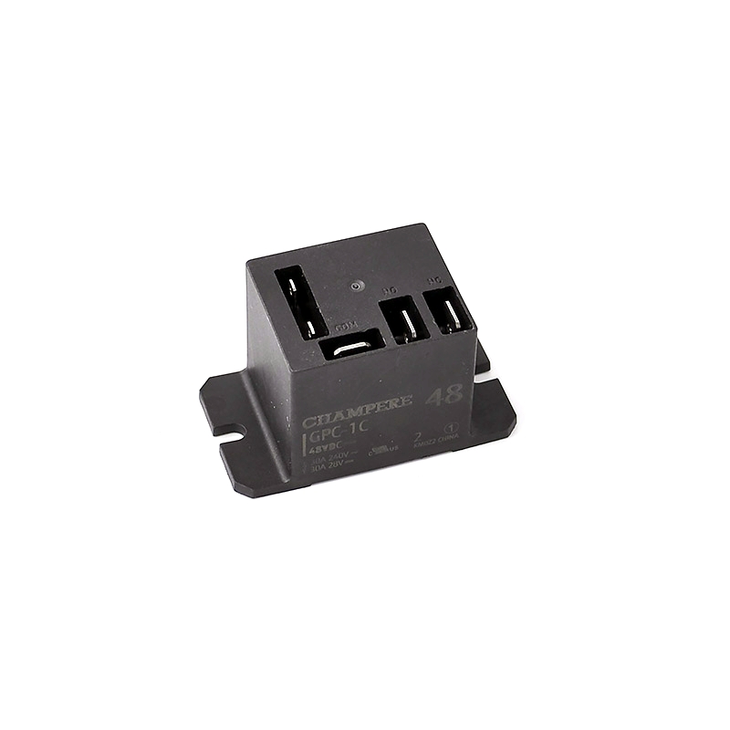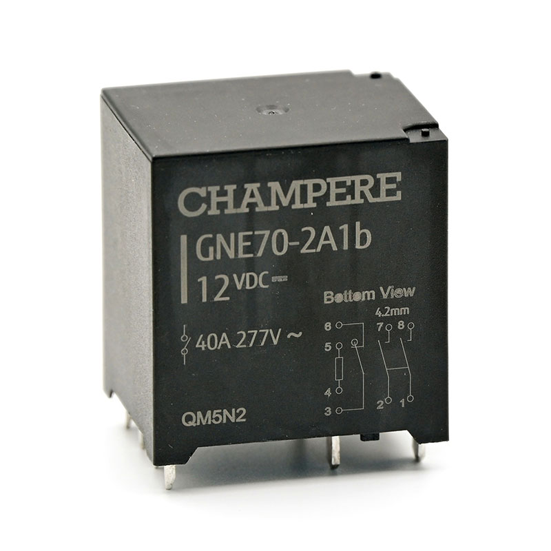
GNE70 Series
40 Amp Rating
- CONTACT & COIL
- CHARACTERISTICS
- Model Info.
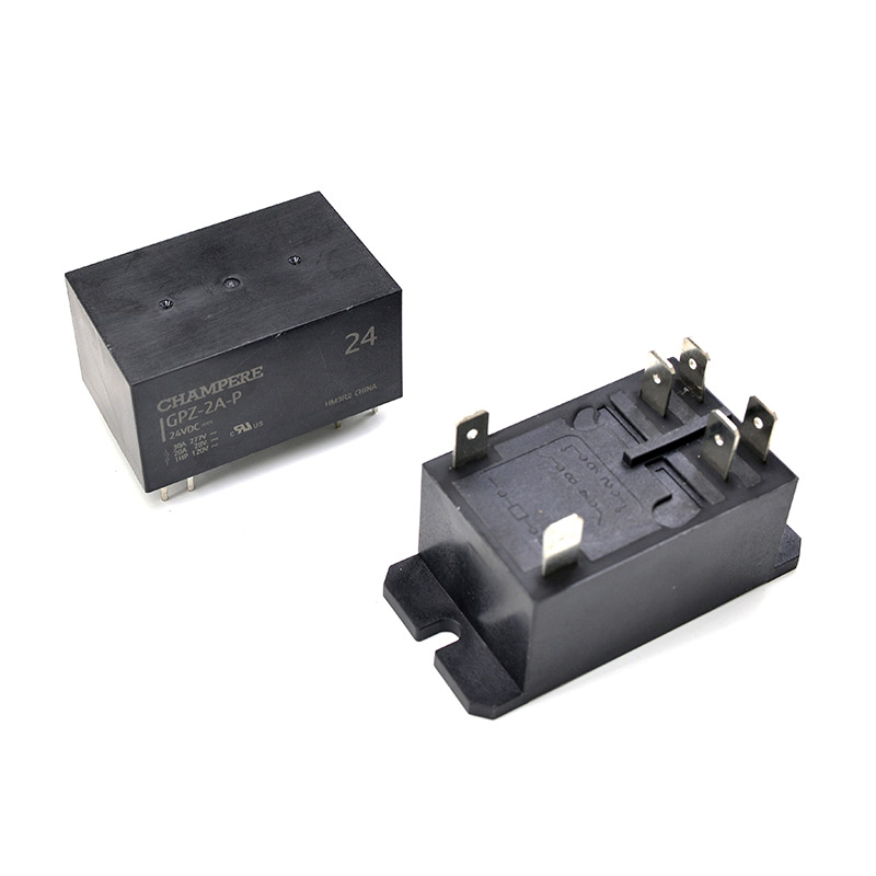
- Drawings & Dimensions
- Precautions
Description
| CONTACT RATINGS | |||
|---|---|---|---|
| Contact Form | 2A, 2A1b | ||
| Contact Res. | Main Contact | ≤10mΩ (6VDC 20A) | |
| Auxiliary Contact | ≤100mΩ (6VDC 1A) | ||
| Contact Material | Main Contact | Ag Alloy (AgSnO2) | |
| Auxiliary Contact | Ag Alloy (AgNi) | ||
| Rated Load | Main Contact | 40A 277VAC | |
| Auxiliary Contact | 1A 277VAC/30VDC | ||
| Max. Voltage | Main Contact | 480VAC | |
| Auxiliary Contact | 277VAC/30VDC | ||
| Max. Current | Main Contact | 40A | |
| Auxiliary Contact | 1A | ||
| Max. Power | Main Contact | 11,080VA | |
| Auxiliary Contact | 277VA/30W | ||
| Min. Load | 100mA at 12VDC | ||
| COIL DATA | |||||
|---|---|---|---|---|---|
| Coil Power | Approx. 1.88W | ||||
| Rated Voltage (VDC) | Operate Voltage (VDC) | Release Voltage (VDC) | Max. Voltage (VDC) | Holding Voltage | Coil Res. (Ω)±10% |
| 6 | ≤4.5 | ≥0.3 | 6.6 | 30% to 100% UN (at 25°C) 40% to 60% UN (at 85°C) |
19.1 |
| 12 | ≤9 | ≥0.6 | 13.2 | 76.6 | |
| 24 | ≤18 | ≥1.2 | 26.4 | 306.4 | |
Additional information
| Weight | 66 g |
|---|---|
| Dimensions | 36 × 30 × 40 mm |
| Max. Capacity | 40A 277VAC |
| Contact Form | 2 Form A |
| Aux. Contact Form | Nil, 1b |
| Operate Time | ≤30ms |
| Release Time | ≤10ms |
| Coil Power | 1.88W |
| Insulation Resistance | 1,000MΩ (@500VDC) |
| Dielectric Strength (I/O) | 5,000VAC 1min |
| Dielectric Strength (O/O) | 2,000VAC 1 min |
| Dielectric Strength (Contact Sets) | 2,000VAC 1min |
| Shock Resistance | Non-energized: 10G; Destructiion: 100G; Malfunction: 10G |
| Vibration Resistance | Destruction: 10 to 55Hz (Double Amplitude); Malfunction: 10 to 55Hz (Double Amplitude) |
| Ambient Temperature | Operating: -40℃ – 85℃ |
| Ambient Humidity | Operating: 5% – 85% |
| Mount Type | PCB Pin (DIP/TH) |
| Color | Black |
| Model Number Legend | ||||||||||
|---|---|---|---|---|---|---|---|---|---|---|
| GPZ | – | 2 | A | 1b | – | F | 12VDC | |||
| (1) | (2) | (3) | (4) | (5) | ||||||
| (1) | NO of Pole: | 2: 2 Pole. | ||||||||
| (2) | Main Contact Form: | A: Normally Open. | ||||||||
| (3) | Aux Contact Form: | 1b: 1 Form b / Normally Closed | ||||||||
| (4) | Insulation Class: | F: Class F | ||||||||
| (5) | Coil Voltage: | X / XX VDC: Coil Voltage Value. | ||||||||
| Major Model Ordering Chart | ||||||
|---|---|---|---|---|---|---|
| NO of Pole | Main Contact Form | Aux Contact Form | Mount Type | Insulation | Model | Coil Voltage |
| 2 Pole | DPST | 1b | 40A | Class F | GNE70-2A1b-F | 12VDC 24VDC |
| Nil | GNE70-2A-F | |||||
For standard type, materials used already meet Class F insulation requirements.
When ordering, add rated coil voltage to model.

PRECAUTIONS REGARDING COIL INPUT
For the operation of AC relays, the power source is almost always a commercial frequency (50 or 60 Hz) with standard voltages of 6, 12, 24, 48, 120, 230 and 240VAC. Due to this, when the voltage is ohter than the standard voltage, the product becomes special model.
PRECAUTIONS REGARDING CONTACT
For the operation of AC relays, the power source is almost always a commercial frequency (50 or 60 Hz) with standard voltages of 6, 12, 24, 48, 120, 230 and 240VAC. Due to this, when the voltage is ohter than the standard voltage, the product becomes special model.
PRECAUTIONS REGARDING SOLDERING CONDITION
We recommend wave solder, the recommended temperature is 240°C 464°F to 260°C 500°F, and the time is 2s to 5s, time should no longer than 2s when temperature reach 250°C 500°F or above.